
Machined Pendant
September 2019 - December 2019
I designed and machined an intricate, dual sided stainless steel pendant, complete with brass screws and engraved details. The process included use of Solidworks to generate geometries, a manual lathe, a drill press, a threading tool, a manual mill with CNC engraving capability, and sanding machines to create a glossy finish.


Design
I designed both the pendant top and rear in Solidworks with interesting patterns. A photo of the Solidworks rendering of the pendant top is shown at the left.

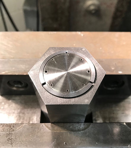
Turning
Machining began by turning aluminum rods to the correct diameters using a manual lathe. I also used the lathe to turn the pocket into the back piece of the pendant. After the correct geometries were machined into the rods, I used a piece of sandpaper to finish off the faces to make them shiny and smooth. Once finished, I took the part out of the collet, reversed it, and placed it back inside, where I then cut the part out from the stock at the correct depth.
Drilling
I drilled 6 phantom holes and 2 through holes into the top portion of the pendant, since the phantom holes would not be used for securing the top to the bottom. The same holes were generated in the same places on the bottom piece. I used 0-80 brass screws in the finished design.
Engraving
I used an engraving tool on a manual mill to engrave the fine detail on the top and bottom of the piece. I programmed the path that the mill took into the CNC on the readout by importing it from Solidworks geometry. Multiple passes of the same path was taken on both the top and bottom piece to ensure that depth would be cut without jeopardizing the detail.


Finishing
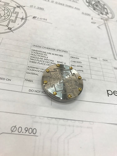
Once all of the geometry was made and holes drilled, I finished the piece by threading the holes on both the top and bottom pieces and sanded the faces again to ensure a good surface finish. I filled the geometry on the back piece with black paint and let it dry. Finally, I assembled the two pieces with 0-80 brass screws.
Final Product


